| The Ovation Fan Club | ||
| ||
| Random quote: "I've always felt that blues, rock 'n' roll and country are just about a beat apart."-Waylon Jennings |
 1619-4 Rebuild... 1619-4 Rebuild...
| View previous thread :: View next thread | |
| Member Communities -> Bottom Feeding Luthiery Guild | Message format | |
| DanSavage |
| ||
Joined: June 2012 Posts: 2303 Location: Lake Forest, CA | I've never actually held a shiny bowl, so it's difficult for me to say whether the shine was in the fiberglass itself or paint layer that was applied later.
The 1st gen Ovation bowls were also laid up over male molds, but to get the outside smooth, they laid a plastic sheet over the wetted cloth just like I did, and then applied vacuum to suck the visqueen down. Because the photos TJR sent of the 1st gen bowl show the fabric weave as well as the wrinkles and folds of the visqueen vacuum bag, I suspect that Ovation actually sanded, filled, primed and painted the shiny bowls. It would be much easier to add black pigment to the resin and lay up the bowl in a female mold. Then, the bowl would come out of the mold black and glassy smooth.
Edited by DanSavage 2014-05-15 3:40 PM | ||
| |||
| TJR |
| ||
Joined: July 2002 Posts: 288 Location: Maine | Dan. If you create a peripheral lap joint when using your patch , how do you plan to finish the interior ? resin and cloth fill too ? | ||
| |||
| DanSavage |
| ||
Joined: June 2012 Posts: 2303 Location: Lake Forest, CA | trickard - 2014-05-15 8:20 PM Dan. If you create a peripheral lap joint when using your patch , how do you plan to finish the interior ? resin and cloth fill too ? Therein lies my conundrum. I'm less concerned with having a scar on the inside than I am deadening the bowl. One of the desirable features of the early cloth bowls was the sympathetic response, a.k.a. belly rumble. When Ovation went to the SMC bowls, which are thicker, the bowls lost some of this. The Lyrachord GS allowed the bowls to be thinner, which gave back some of this response. So, if I go to the lap joint, it'll be easier and stronger, but I'll be adding thickness to the back of the bowl which will deaden the responsiveness of it. It will definitely be easier to apply a thin reinforcement to the edge glue joint with the top off, which suggests the time to do this is before replacing the top. The more I think about it, the more I'm leaning toward cutting the patch to fit the existing hold, then edge-gluing it into place and if necessary, applying a thin fiberglass lap-joint reinforcement strip to the inside of the bowl. | ||
| |||
| DanSavage |
| ||
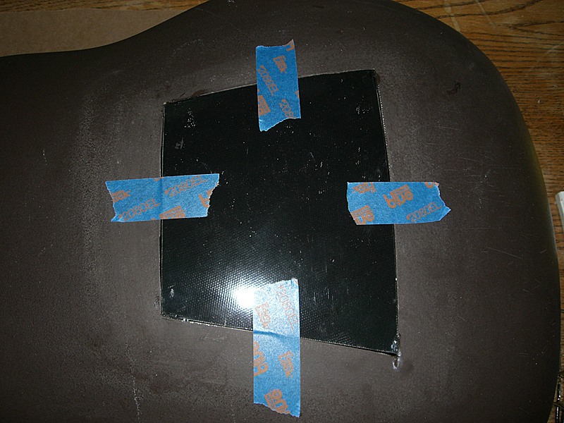
Joined: June 2012 Posts: 2303 Location: Lake Forest, CA | Progress continues.
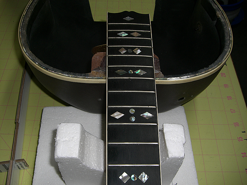
Test fit. Not perfect, but good enough. The part is taped to the inside using masking tape.
I'll probably use my favorite method of edge-gluing fiberglass parts to assure perfect alignment. First, I'll tack-glue the corners with C/A. Next, apply a fiberglass reinforcement strip and resin to the inside. Next up, removing the rest of the top.
Speaking of neck blocks, the factory standards for centering the neck block on the body were pretty loose. | ||
| |||
| DanSavage |
| ||
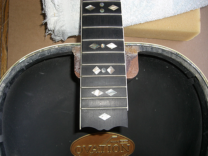
Joined: June 2012 Posts: 2303 Location: Lake Forest, CA | While waiting for my top parts to arrive, I decided to verify the neck angle.
Laying a straightedge on the neck showed that it would hit the bridge about 1/4" too low. Not good. I found a video online where the owner of Blues Creek Guitars was talking about how he sets up the geometry when building for a 28-foot radius top. He said that he liked to have 1/2" space between the top and the bottom of the straight edge. He also said that this usually requires a neck angle of about 1-1/2 degrees. I broke out a level and my trusty incidence meter and measured the neck angle of the Ovations. These are about 1/2 a degree. So, I cut out a section of the top plate simulator I built to simulate a true flat top, and the straightedge is now above the top of the bridge by about 1/16" or so. Much better.
Ovations having, more or less, flat tops makes sense. In the factory tour video one of the workers is shown routing the top for the binding. On a wood box guitar this is done with the body in a jig, face-up on the workbench. But, the Ovation was being routed face-down. This would difficult to do if the top had any kind of radius to it because the top would wobble around and the router would not cut an even groove. Since the braces I ordered are made to work on a 28-foot radus top, I'll need to modify them to work on a flat plate, but that is a minor task. Disaster averted. Edited by DanSavage 2014-05-19 9:25 AM | ||
| |||
| sycamore |
| ||
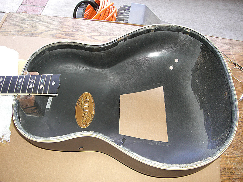
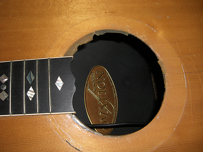
Joined: March 2007 Posts: 698 Location: Cork, Ireland | Why was the hole cut in the back in the first place? | ||
| |||
| DanSavage |
| ||
Joined: June 2012 Posts: 2303 Location: Lake Forest, CA | According to the ad TJR wrote, this was, or could have been, an engineering sample. Having the hole in the back wouldn't affect the playability but would allow access to the internals/electronics without loosening the strings. | ||
| |||
| DanSavage |
| ||
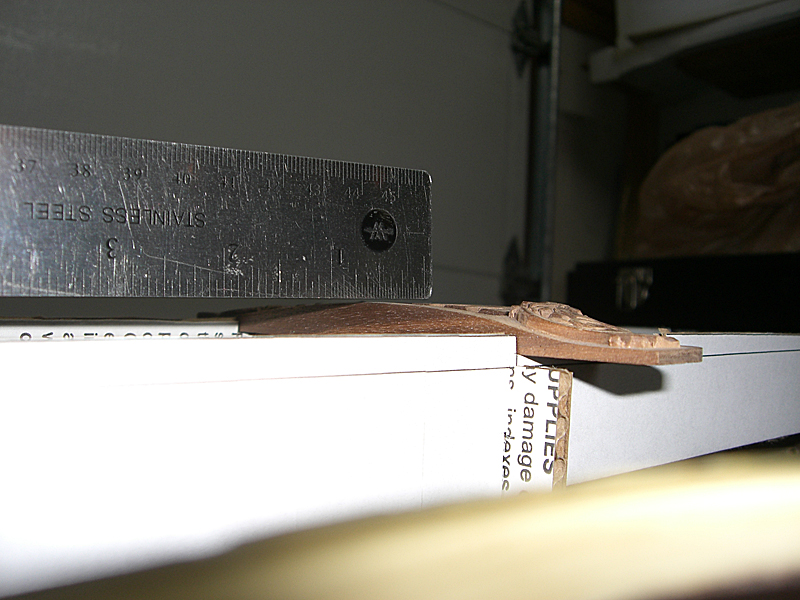
Joined: June 2012 Posts: 2303 Location: Lake Forest, CA | I found out why the neck block was offset. It looks like there was a method to the factory's madness, after all. It wasn't sloppy building. The top strap button was screwed into the neck block. Good job, guys!
Edited by DanSavage 2014-05-19 8:52 PM | ||
| |||
| DanSavage |
| ||
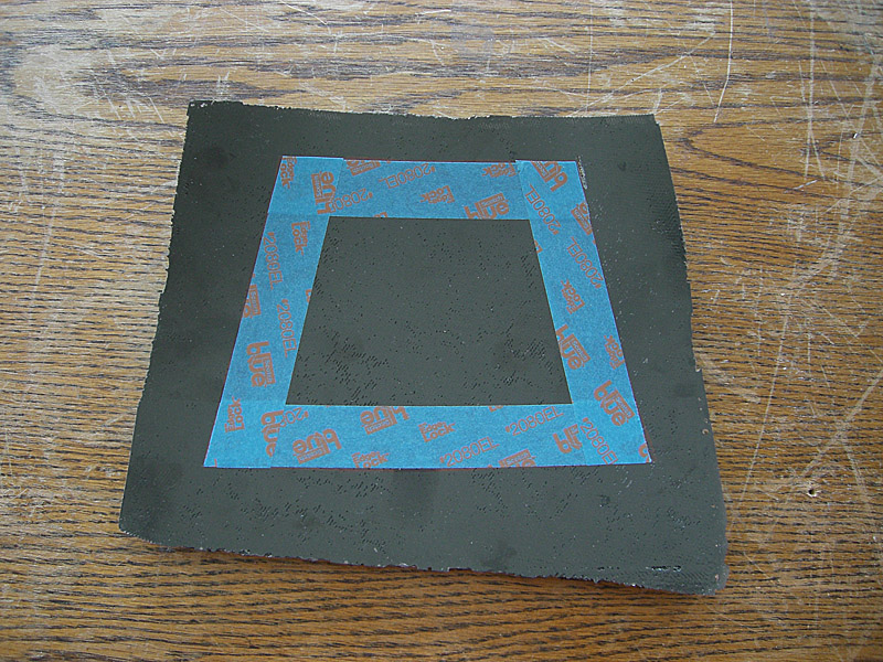
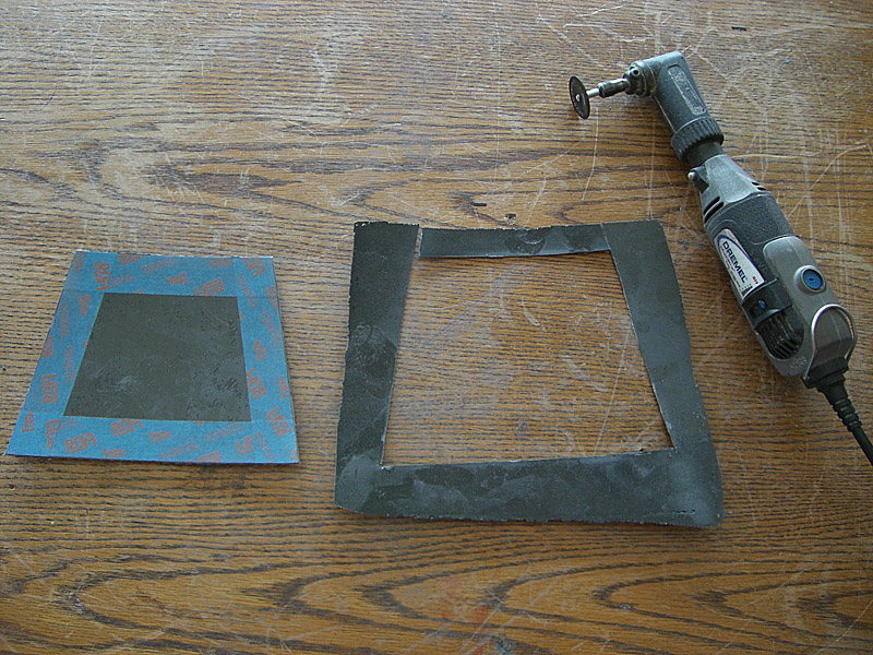
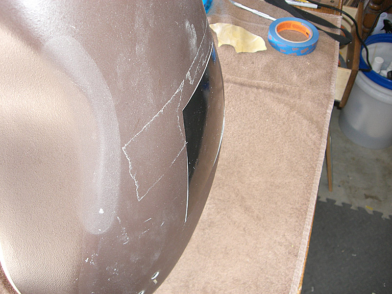
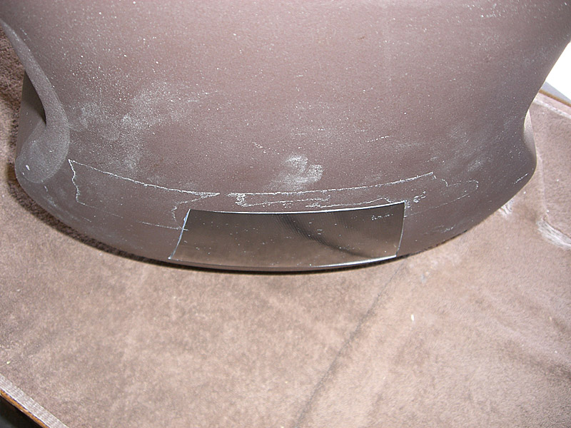
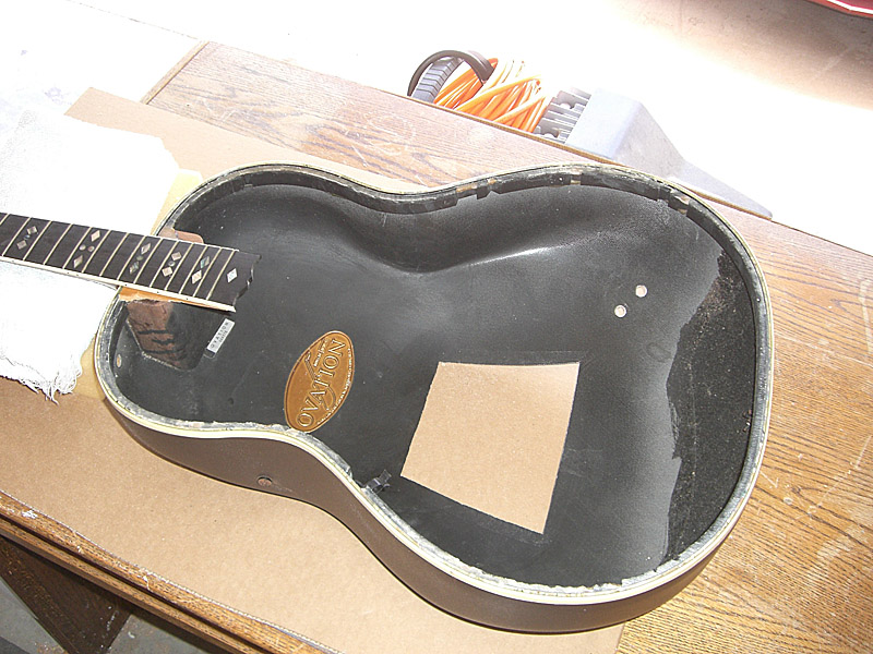
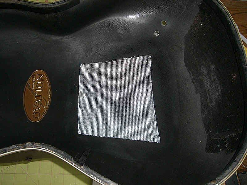
Joined: June 2012 Posts: 2303 Location: Lake Forest, CA | The work continues. First task at hand is to glue the patch into the hole in the back. A short piece of tape on each side to hold the patch in place. Then, each corner is tack-glued with CA.
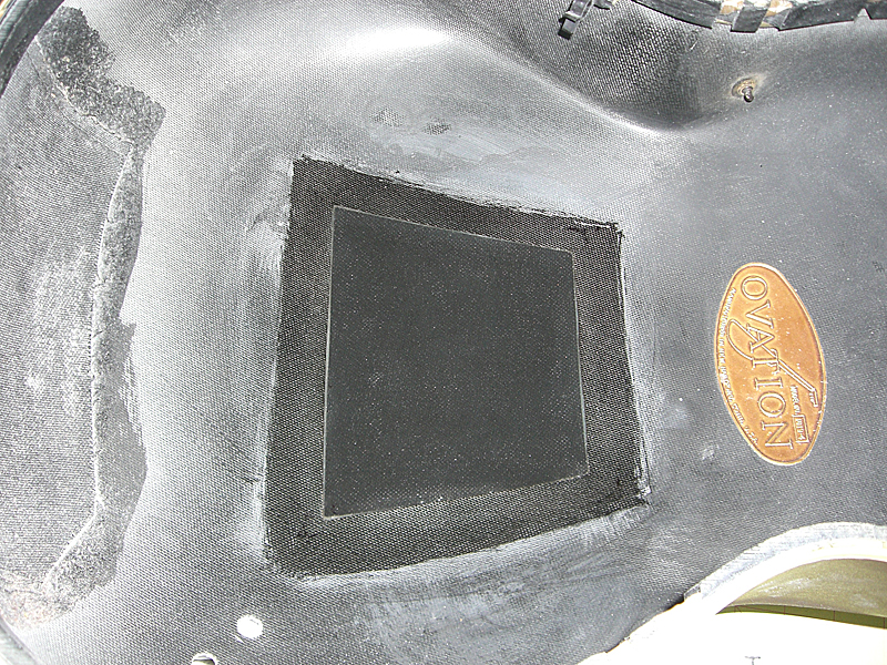
A reinforcement piece is cut from 3-oz. plain weave cloth which is slightly bigger than the patch and fiberglassed into place. When it's dry, the inside is sanded smooth to blend the edges into the surrounding area.
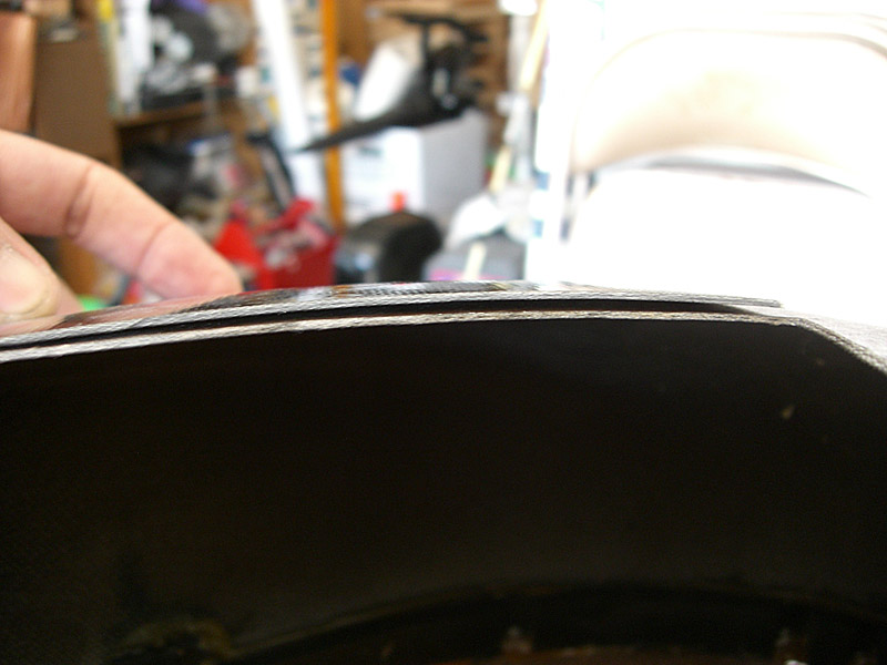
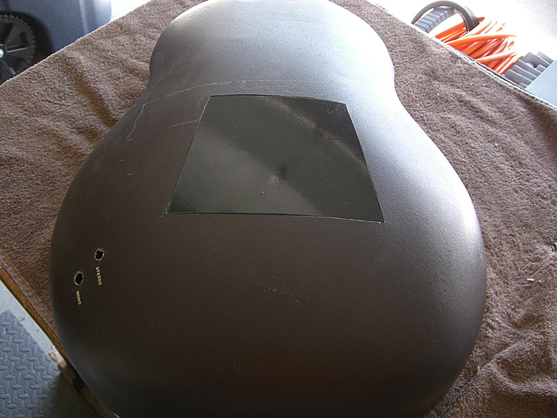
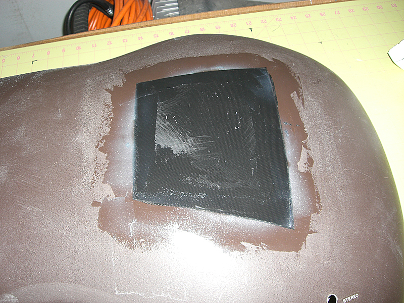
The outside is also sanded smooth. The laminating resin is mixed with cab-o-sil to make a thick putty. This is smeared over the seams to blend the patch into the back. The body is flipped over and a final, thin coat of resin is painted over the reinforcement piece. The body is left to dry overnight. The inside and outside are sanded smooth in preparation for paint.
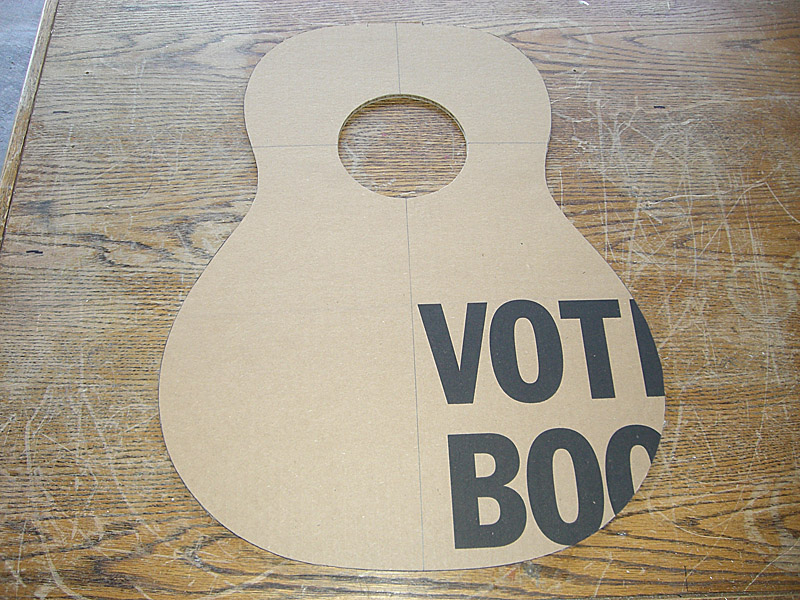
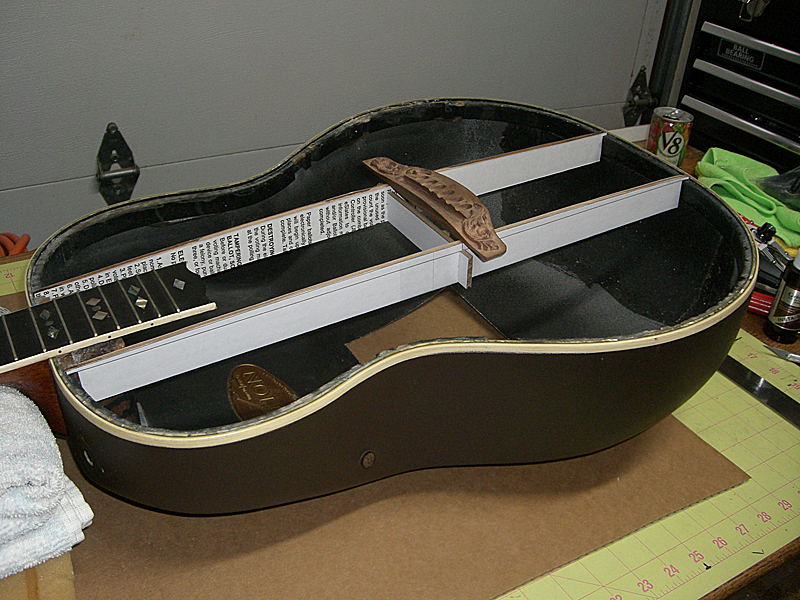
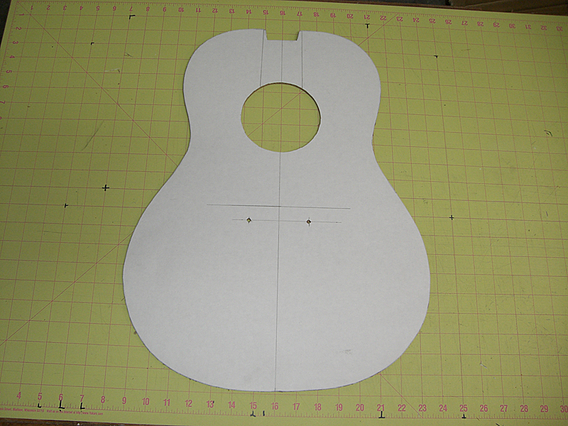
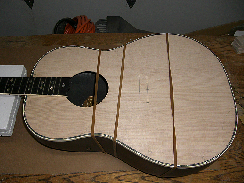
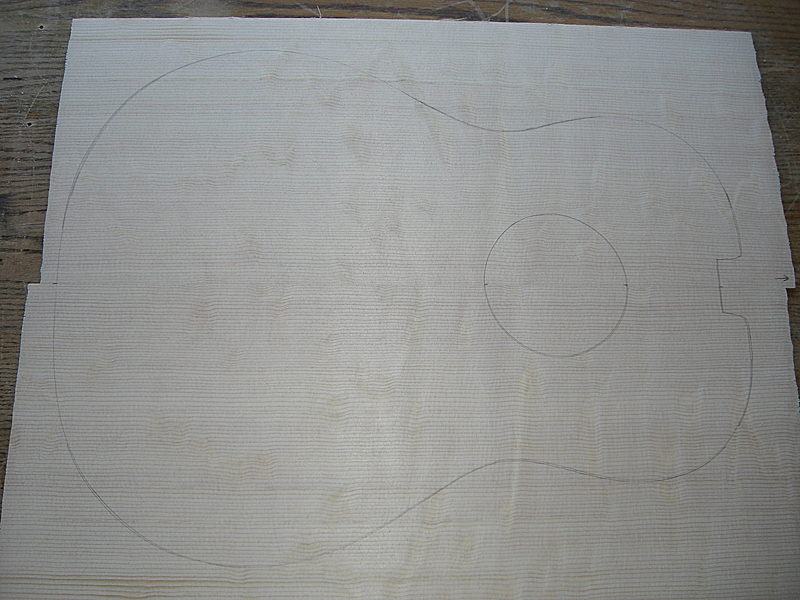
Next up, make a template from cardboard for the top that will fit inside the purfling. Fit is pretty good. This will be used to trace the top wood. I'll leave a little bit of extra wood on the outside and will bevel thei top wood so it will be a slight pressure fit. I bought some binding rubber bands from Stewmac which should squeeze the sides into the top wood.
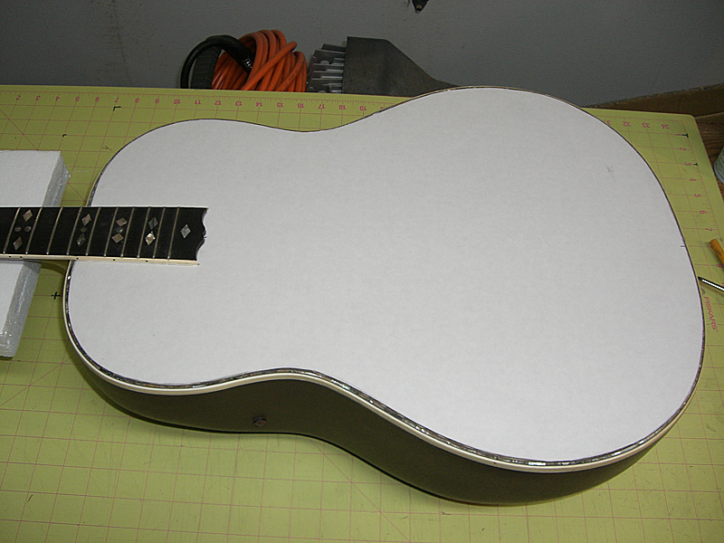
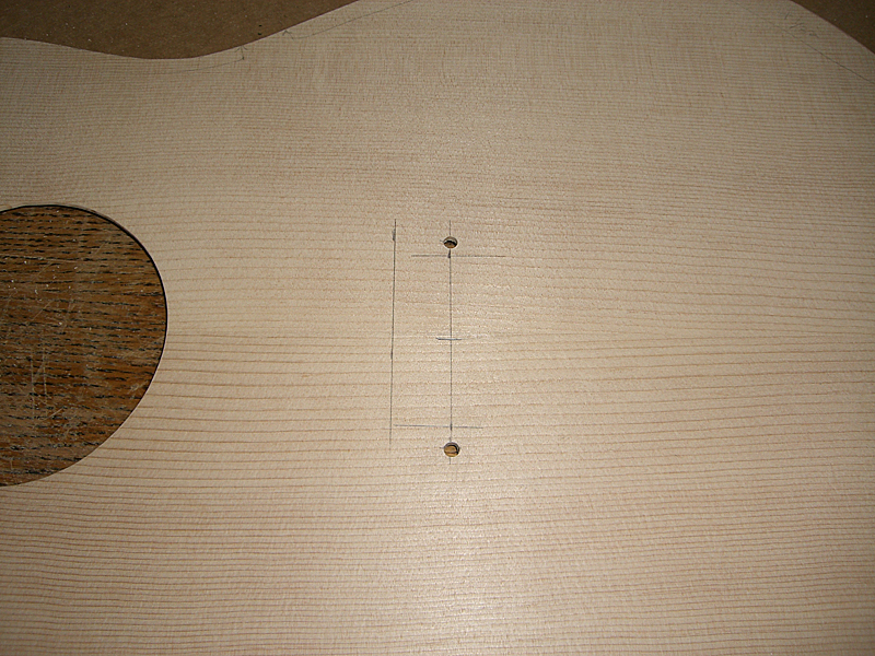
Cut the sound hole for the rosette. Measure and mark the location of the bridge and the locating holes for the alignment pegs glued into the bottom of the bridge.
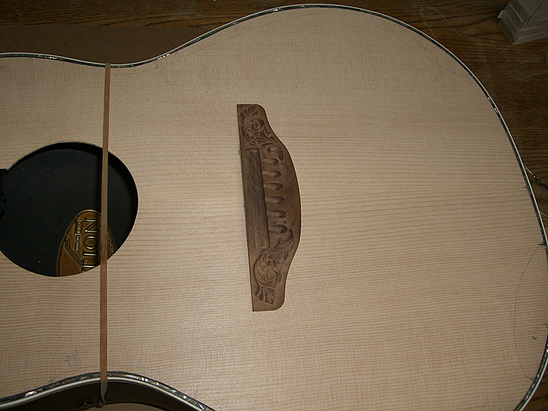
Looks good, but it has the dull sound of cardboard.
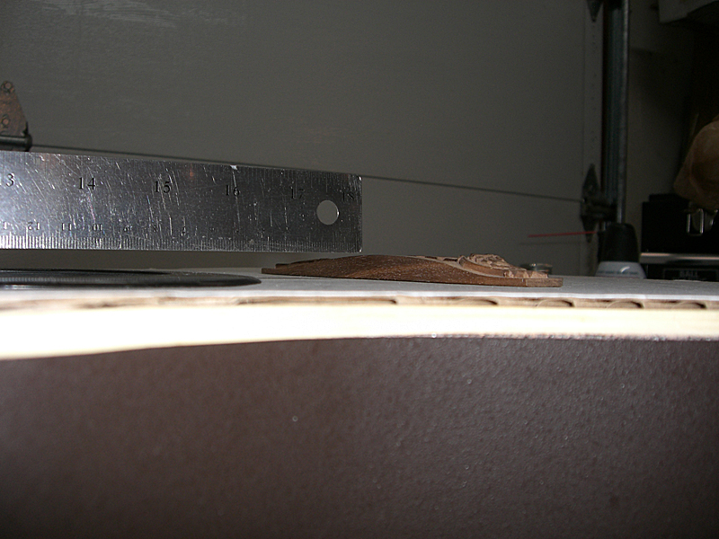
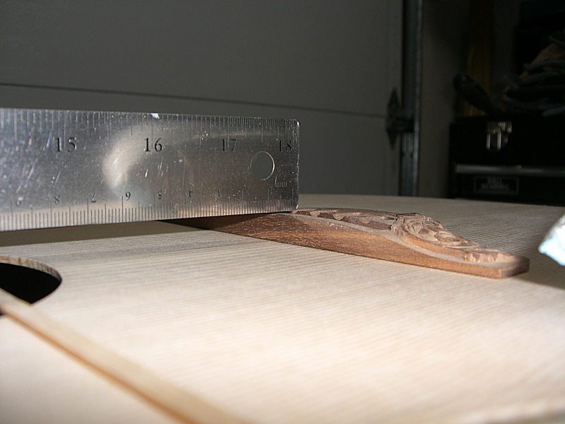
Check the neck geometry. The ruler just touches the top of the bridge. The cardboard is 3/16" and the top wood will be ~3/32", so this should put the bridge in a perfect position for nice, low action with plenty of room to grow.
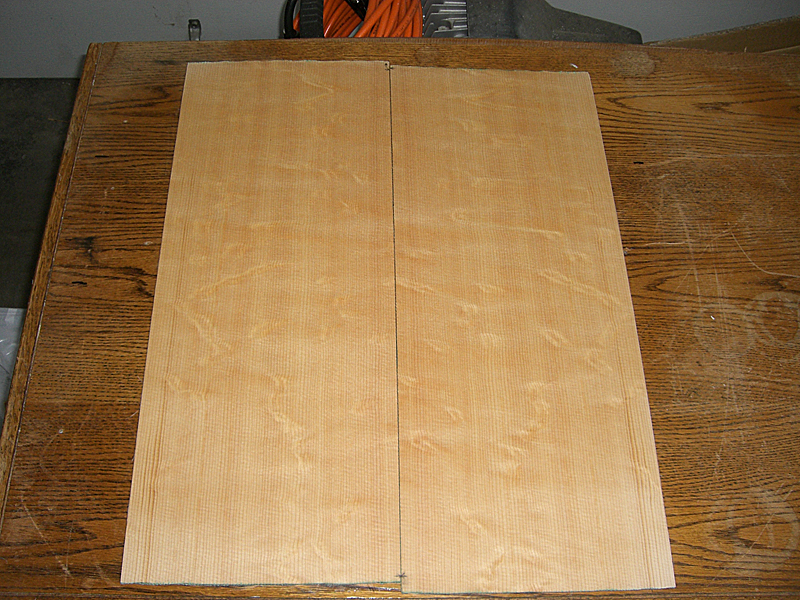
Speaking of top wood, I thought that with what this guitar has been through in its life it deserved to have something special. I bought some Master-grade bearclaw spruce from Stewmac. I sprayed some ZIP Kicker on it to highlight the grain and figuring. (mostly naptha) And, more importantly, it's got a really nice tap-tone. I'm planning to use forward-shifted X brace pattern to give the guitar a nice, bright sound. So, it should make for a nice guitar that sounds as good as it looks.
Next job is to start preparing the braces. Pics to follow. Edited by DanSavage 2014-05-24 6:18 PM | ||
| |||
| marenostrum |
| ||
Joined: August 2007 Posts: 1008 Location: Tuscany, Italy | Very nice and informative....thank you. | ||
| |||
| TJR |
| ||
Joined: July 2002 Posts: 288 Location: Maine | Dan, so what exactly are you using to cut the cardboard templates. I see you're using a CAD program to plot out various lines. Are you hand cutting all the shapes or do you have a CNC router type device? The form of your cardboard top to fit inside the purfling looks like a pretty darn good fit. | ||
| |||
| TJR |
| ||
Joined: July 2002 Posts: 288 Location: Maine | I forgot to add that your patch panel to the back looks really really great. It will hardly be noticeable through the sound hole. This has been great following your progress. | ||
| |||
| 2wheeldrummer |
| ||
Joined: February 2014 Posts: 699 Location: moline,illinois | You are doing some amazing work its really cool to follow your progress! | ||
| |||
| DanSavage |
| ||
Joined: June 2012 Posts: 2303 Location: Lake Forest, CA | trickard - 2014-05-25 8:18 AM Dan, so what exactly are you using to cut the cardboard templates. I see you're using a CAD program to plot out various lines. Are you hand cutting all the shapes or do you have a CNC router type device? The form of your cardboard top to fit inside the purfling looks like a pretty darn good fit. ... I forgot to add that your patch panel to the back looks really really great. It will hardly be noticeable through the sound hole. This has been great following your progress. Hi TJ, Just a #11 Xacto blade. Actually, those lines are pencil-drawn. Yes, all the shapes are hand-cut. I have the ability to have parts laser-cut by a guy locally who cut the parts for my model airplane kits, but for this project I'm cutting all the parts by hand. I've always hand-cut the parts for the prototypes of my kits, mainly because it's cheaper and faster than sending the parts out to be cut. Also, the photos don't show it, but this bowl is actually slightly asymmetrical in the lower bout. The cardboard top you're seeing is actually the second one I cut. I originally put the bowl upside-down and traced it. That was the one in the one I posted earlier. I drew a line that was the offset by the thickness of the binding/purfling and cut out that template. When I tried putting it inside the purfling, it ended up being wrong in a lot of places. So, I took that one and traced a new one, then redrew the lines where it was off and hand-fitted that to the top recess. It required shaving here and there to get a decent fit. It's not 100% perfect, but it's a good starting point. When I ordered the bearclaw spruce, I also ordered some cheapo top wood. I'm going to use that as the preliminary test piece, which will be cut slightly large. I'll taper the back slightly so it'll be a gentle press fit with the top surface mating to the inside of the purfling. Then, once I'm happy with the fit, I'll use that as the final template to cut the bearclaw spruce. I didn't get a perfect edge glue joint with the patch. The patch ended up being slightly offset to outside, which is why I had to use the filler putty on the outside. Like you say, it won't really be visible through the sound hole and the outside of the joint is smoothly faired, so once I repaint the bowl with the textured paint, the joint should be pretty much invisible. The patched area has a consistent tap tone with the rest of the back, so I'm happy with it. Thanks for the kind words, everyone. I'm glad you all are enjoying it. Edited by DanSavage 2014-05-25 4:44 PM | ||
| |||
| DanSavage |
| ||
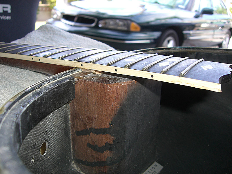
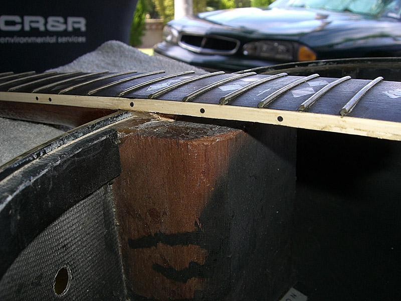
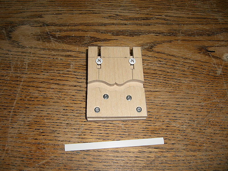
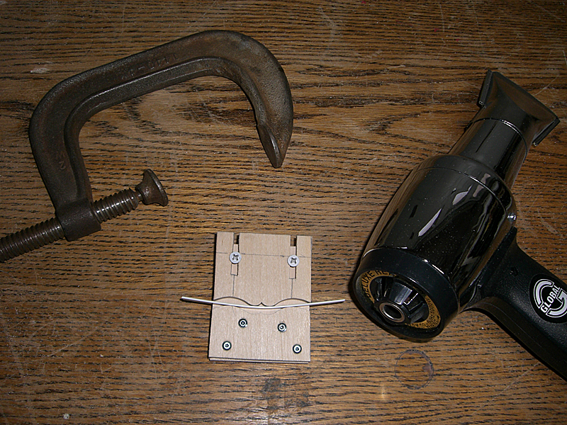
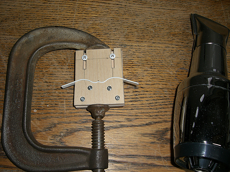
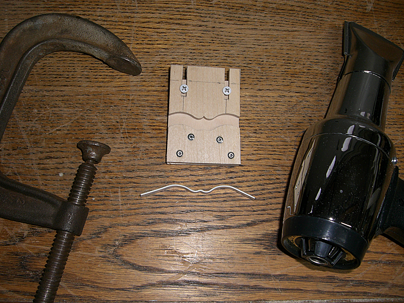
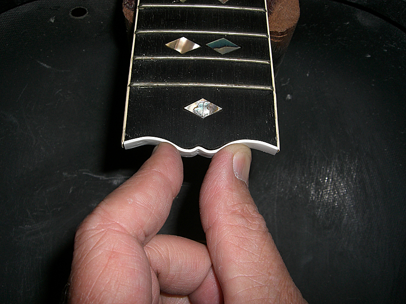
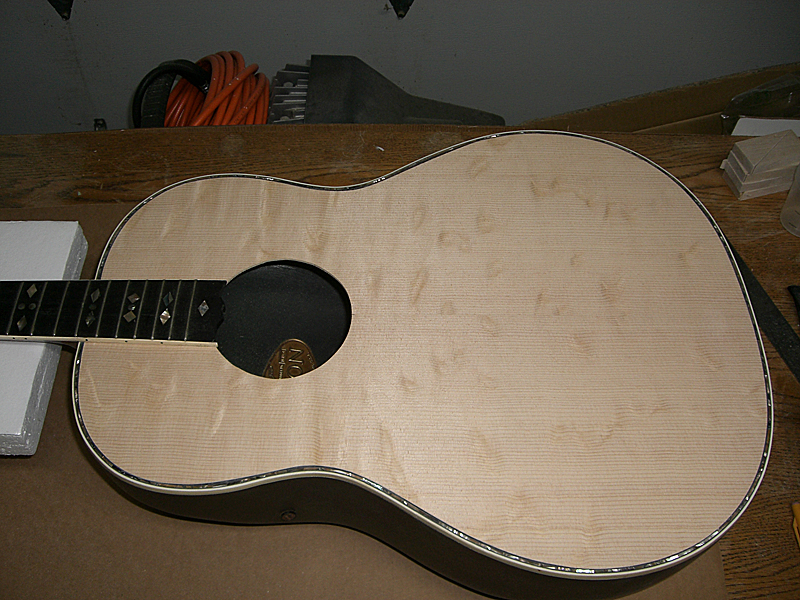
Joined: June 2012 Posts: 2303 Location: Lake Forest, CA | A side job that needs to be done before gluing the top into place is to replace the missing binding around the end of the fretboard.
Once it cooled, I popped it out of the mold and it retained the correct shape.
And, here's the final piece, trimmed to fit. Actually, this isn't the final piece because the binding I bought is white and the binding on the guitar is ivory-colored. I bought some cream-colored binding from Stewmac, but it's too dark, so I can't really use that, either.
I searched around online and found what looks like the right color binding from a company called, Allparts.com. If it's the right color, I'll make a new patch, glue it into place, then scrape it to match the profile of the fretboard. Edited by DanSavage 2014-05-29 1:00 AM | ||
| |||
| MWoody |
| ||
Joined: December 2003 Posts: 13983 Location: Upper Left USA | Coming along nicely! | ||
| |||
| seesquare |
| ||
Joined: November 2002 Posts: 3599 Location: Pacific Northwest Inland Empire | Nice work, Dan! With all the jigs & molds required, do you have an honored place in your shop, where you display these contraptions, to remind yourself, and any other interested parties, what a labor-of-love these projects can become? As I recall, from the halcyon days of my misspent youth, there were at least 20 different devices that were custom-made, to get vintage automobile restorations accomplished, hanging in the shop. The most memorable one was the jig we made out of Ponderosa Pine, done on a camping trip at Yosemite National Park, circa 1961, for filing a differential bushing, for a 1928 Model "A" sedan. A couple of grad students from San Francisco State broke down, and were pretty-well stuck for parts & repair, until rescued by The Old Man, & my uncle. Took them 3 days, and copious amounts of fine bourbon, as I recall, to fabricate that part from a piece of oak wood, and get it installed. Got the guys back to Frisco, about a 200-mile trek! Edited by seesquare 2014-05-29 8:44 AM | ||
| |||
| DanSavage |
| ||
Joined: June 2012 Posts: 2303 Location: Lake Forest, CA | Thanks! That's a great story.
| ||
| |||
| seesquare |
| ||
Joined: November 2002 Posts: 3599 Location: Pacific Northwest Inland Empire | Hmmmmmm..........a clean workshop. Novel concept. | ||
| |||
| DanSavage |
| ||
Joined: June 2012 Posts: 2303 Location: Lake Forest, CA | Actually I just strategically aimed the camera so you couldn't see the floor. One whole side of the garage looks like a NYC street during a garbage strike. Edited by DanSavage 2014-05-29 11:58 AM | ||
| |||
| MWoody |
| ||
Joined: December 2003 Posts: 13983 Location: Upper Left USA | Note to self: devise and market guitar case hangars for the ceiling... and clean up the shop. | ||
| |||
| DanSavage |
| ||
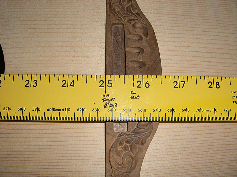
Joined: June 2012 Posts: 2303 Location: Lake Forest, CA | When I bought my top wood, I bought the bearclaw spruce, which is what I'm planning to use and I bought some cheap spruce I could use as a practice piece. I'd planned to use hot hide glue (HHG) where ever possible. There are three main reasons for this. First, it's easier to disassemble, should the need arise, secondly, it has a stronger grip on wood/wood joints and lastly because it carries the tone better than any other glue like epoxy or PVA. One of the first HHG joints was to join the halves of the top wood. I did the practice piece and was very happy with the results, so I did the final wood next. I found a local furniture shop that was able to thickness sand the two tops for me for $30. As it turns out they do a lot of this type of work for luthiers in my area. I cut out the practice top and fitted it to the bowl. I wanted to verify the height of the bridge, so I marked the location. Seen in the pic below are the additional notes around the periphery of the top are where I needed to make adjustments when tracing outline of the practice top onto the final top.
I used a 3/16" brad-point bit and drilled the locating pin holes in the pracice top. I'll need to do this with the final top before adding the bracing.
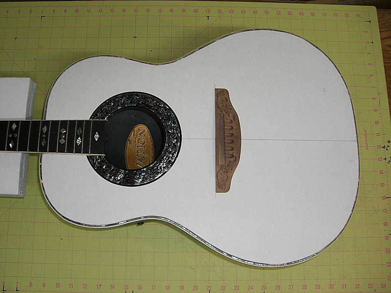
The top is back in the bowl and the bridge is put into place.
A quick check reveals there is a gap of about 1/16" between the straight edge and the top of the bridge, which is perfect. Bridge location on the top is also spot-on.
I traced the top outline to the final top wood, cut it out and started the final fitting. It fits pretty good, but I still need to make a few minor adjustments. Mostly, I'm pretty happy so far.
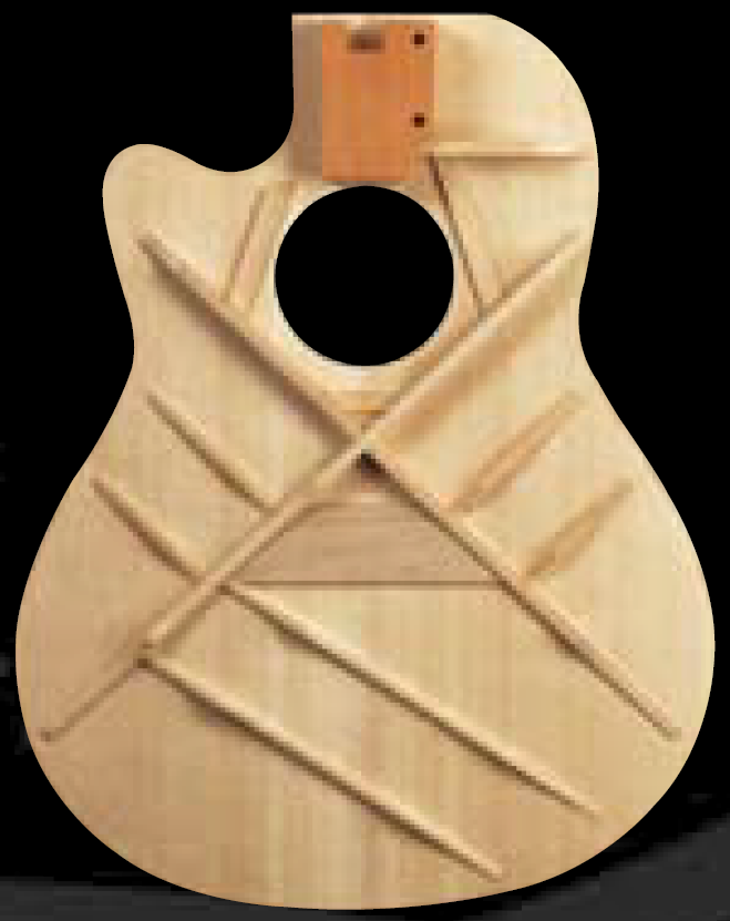
I've been thinking a lot about what X-bracing pattern I wanted to use. I was originally going to use a forward-shifted X-brace. But, after playing my 2078-TX I've decided to use the Ovation LX bracing. The LX bracing is very similar to the standard X brace pattern except for minor adjustments to the angle of the X braces. Standard X-braces are layed out with a 98-degree angle and the LX braces have a 95-degree angle. The 2009 Ovation catalog contains pics of the LX bracing for both the center hole and the epaulet-style tops. I've imported the photo below into my CAD program and I'm tracing the braces locations with the intention of printing out a full-size plan. Even though the photo below shows a cut-away bowl, the braces are identical with standard bowl except for the to brace above the sound hole. It's been shortened for the cut-away bowl. On the standard bowl it goes all the way across the top. I'll use this plan to lay out the braces on the top wood.
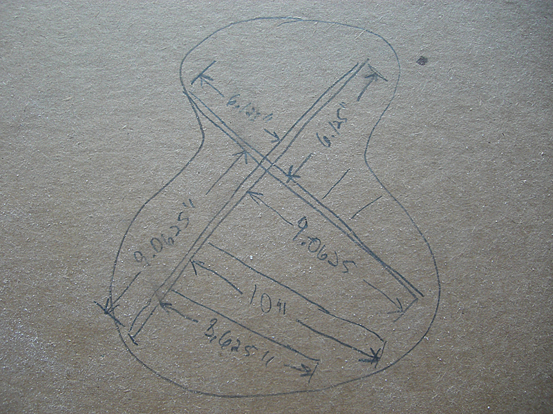
I took some measurements from my 2078-TX which will help me to scale the plans.
| ||
| |||
| SOBeach |
| ||
Joined: April 2010 Posts: 823 Location: sitting at my computer | Really interesting and informative thread! Great job Dan | ||
| |||
| MWoody |
| ||
Joined: December 2003 Posts: 13983 Location: Upper Left USA | BFLG porn! | ||
| |||
| DanSavage |
| ||
Joined: June 2012 Posts: 2303 Location: Lake Forest, CA | Thanks for the kind words, Jeffrey. I'm glad you're enjoying this. MWoody, Don't touch that dial! More BFLG porn coming up shortly. Edited by DanSavage 2014-06-06 2:23 PM | ||
| |||

 .
.


| Jump to page : < 1 2 3 4 5 6 7 > Now viewing page 2 [25 messages per page] |
| Search this forum Printer friendly version E-mail a link to this thread |
| This message board and website is not sponsored or affiliated with Ovation® Guitars in any way. | |
| (Delete all cookies set by this site) | |